Network rack deployment
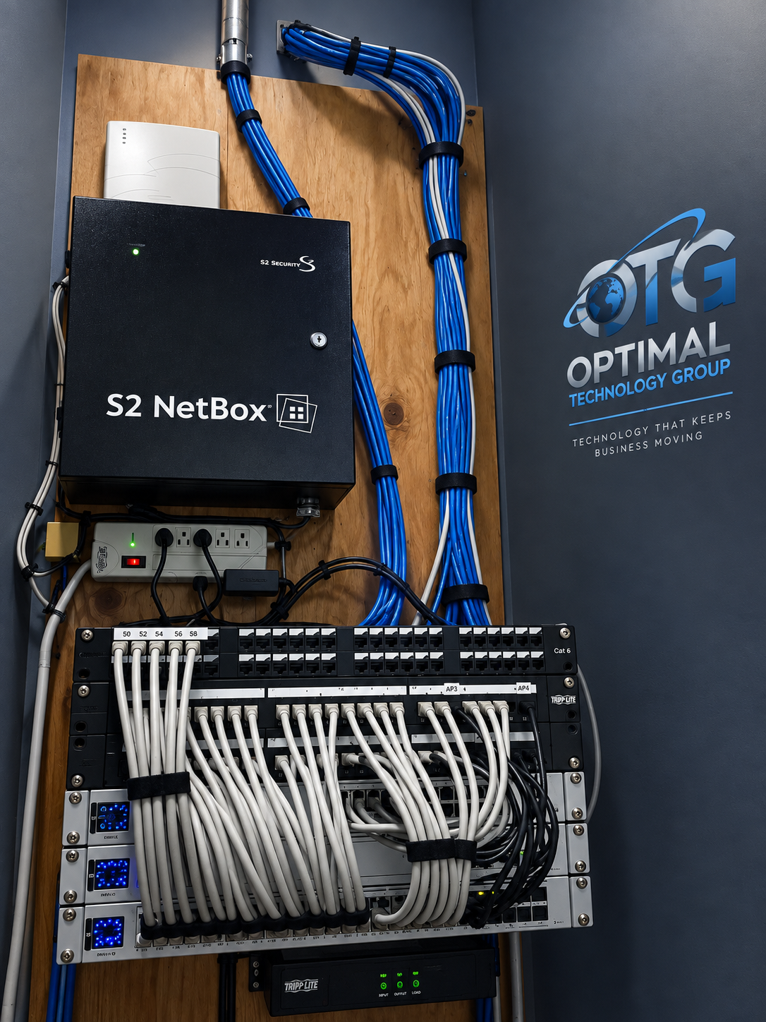
A network project reaching beyond the rack
This Optimal Technology Group network rack deployment included switch replacement, 48 new cables, additional wireless access points, cable management, network drops across more than seven walls, network connections to robots, and fiber added to the network. Those activities describe a project that extended from the equipment rack into the places where connected technology was needed. The rack remained an important part of the infrastructure, but the work also involved distributing connections around the site and connecting equipment beyond the rack itself.
The project brings several parts of physical network infrastructure into one account. Switches provide connection points for network equipment. Cabling carries connections between those points and their destinations. Access points extend wireless connectivity through equipment connected to the network. Wall drops make wired connections available in specific areas, while robot connections bring another type of site equipment into the network scope. Fiber adds a further connection medium. Cable management addresses how those different physical connections are arranged around equipment and pathways.
These elements should be understood together. Replacing switches is one part of the job; providing usable physical routes to equipment is another. Adding access points involves a different device type from adding wall connections, yet both relate to the site’s broader network infrastructure. In this project, OTG’s confirmed work crossed those boundaries. The account below explains each documented part of the installation and how it relates to the rest of the scope, without attaching unsupported performance numbers or customer outcomes to the work.
Replacing network switches
Switch replacement was one of the confirmed activities in this network rack deployment. A switch provides interfaces through which connected equipment can communicate across a network. Physically replacing a switch therefore involves equipment that sits between multiple connections, rather than a standalone device with no relationship to the surrounding cabling. The existing connections, the replacement equipment, and the physical arrangement around the rack are relevant to understanding that type of work.
The owner has confirmed that switches were replaced, but has not identified the manufacturer, model, quantity, configuration, or reason for replacement. Those details should not be inferred from the photograph. The project should also not be described as a specific speed upgrade, a change in network architecture, or a redundancy improvement without further confirmation. A precise case study can state the equipment activity that occurred while leaving unsupported technical specifications out of the narrative.
Within the confirmed scope, switch replacement sits alongside the addition of new cabling and other connections. That relationship is useful for readers planning similar work: network equipment and its physical connections need to be considered together. A request concerning rack equipment may also involve destinations elsewhere in the building, additional connected devices, or changes to cable organization. For this project, the owner has confirmed that the scope included all of those broader physical activities, rather than switch replacement alone.
Deploying 48 new cables
OTG deployed 48 new cables as part of the project. This is the confirmed cable count, and it should remain distinct from the number of wall outlets, switch ports, connected devices, or fiber strands. Those quantities are not automatically interchangeable. A cable count describes the amount of new cable deployment reported by the owner; it does not establish the exact arrangement of endpoints or the type of every cable installed.
The new cabling forms a substantial part of the documented scope. Physical network connections require paths between equipment and the areas being served. The route, termination points, relationship to existing equipment, and access to the installation areas all affect how such work is defined. In this account, the verified fact is the deployment of 48 new cables. Cable category, total length, pathway construction, termination method, and certification results have not yet been provided, so the article does not present them as completed activities.
For a business reader, the count helps distinguish this project from a single connection change. It describes multiple new physical connections within a broader network installation. It also gives context to the other confirmed activities: wall drops, access points, robot connections, switch replacement, and cable management were part of the same project. The case study can explain that combined scope without claiming that every new cable served one particular device type or that all 48 followed identical installation paths.
Network drops across more than seven walls
The owner confirmed that network drops were added on more than seven walls. This detail shows that the project extended network connection points into several physical areas. The work was not confined to arranging equipment inside a rack. It included bringing connections to destinations around the site, where the relationship between an equipment location and the available network infrastructure becomes especially relevant.
The wording matters. More than seven walls is the supplied description of the installation’s reach; it is not an exact count of rooms, departments, buildings, floors, or outlets. Those details have not been confirmed. The article therefore uses the owner’s stated scope rather than expanding it into a more specific site layout. Likewise, the existence of wall drops does not establish which people or devices used each connection after installation.
Wall connection points are a practical part of business infrastructure because equipment is often used away from the central rack. A project may need to connect the rack’s network equipment with work areas, equipment locations, or other agreed destinations. In this project, the owner confirmed that wall drops formed part of that distribution work. Readers can see the physical breadth of the scope while keeping the limits of the available information clear.
Adding wireless access points
Additional access points were included in the same network rack deployment. Access points are a different part of the physical network from wall drops or switches, but they still depend on the network infrastructure around them. Their inclusion shows that the project addressed wireless equipment alongside wired connections. The owner has specifically clarified that these access points belong to this network project; they should not be used as evidence for a separate wireless case study.
The available details do not establish how many access points were added, where each was located, whether existing access points remained in service, or what equipment models were used. They also do not establish a measured improvement in signal coverage, throughput, roaming, or user experience. Those claims require information beyond the confirmation that access points were added. A factual project description should keep the installation activity separate from any performance result that has not been documented.
For readers considering a combined wired and wireless project, this part of the scope illustrates why equipment categories often overlap in a site request. The physical network may need connections for wireless hardware as well as connections for other devices. That does not mean every site requires the same arrangement. It means the requested equipment and its locations help define the physical work. This particular project included both access point additions and the other network activities described here.
Connecting the network to robots
The network work also included running network connections to robots. This is an owner-confirmed part of the project and an important distinction from a description limited to ordinary office computers. It identifies a specific class of connected equipment within the scope. The article does not identify the robots, their manufacturer, their function, or the site where they were used because those details have not been supplied for publication.
A network connection to equipment should not be confused with programming that equipment, changing its control logic, or guaranteeing its operating performance. The confirmation concerns the network connections. It does not establish that OTG configured robotic applications, altered production systems, integrated control software, or performed equipment safety validation. Keeping that distinction clear prevents a physical infrastructure case study from implying a broader engineering scope than the owner has described.
The robot connections also help explain why the project reached beyond the rack. The network needed to connect with equipment at its actual destination, rather than ending at the central equipment location. The cable paths and connection points were therefore part of a broader physical distribution task. The article can describe that reach accurately while avoiding unsupported claims about operational uptime, production capacity, automation performance, or other outcomes that would need separate evidence.
Adding fiber to the network
Fiber was added to the network as part of the same project. This is another confirmed component of the scope, alongside the new cables, wall drops, access points, robot connections, and switch replacement. It indicates that the installation involved more than one kind of network connection work. However, the owner has not yet supplied the fiber type, strand count, route length, connector details, transceiver models, or connection speed.
Those missing specifications matter when describing fiber work. The presence of fiber alone does not prove a particular bandwidth, distance, topology, or resilience benefit. A project account should not infer those properties from an image or from the general capabilities of fiber technology. Here, the factual statement is that fiber was added to the network. More detailed claims can be included later if the owner provides the actual specifications and approves their use in the case study.
At the scope level, the fiber work belongs in the same narrative as the switch and cabling activities. Network infrastructure projects can involve several connection media and several equipment destinations. This project is an example of that combined physical scope, based on the owner’s description. The article deliberately keeps the explanation at that level until the specific implementation details are available, so readers receive an accurate description of the work rather than an assumed technical design.
Cable management as part of the installation
Cable management was another confirmed activity. It concerns how physical connections are arranged around equipment and along the areas in which cables are handled. In a project with switch replacement and new connections, the arrangement of cables forms part of the infrastructure work itself. It should be described alongside the installed equipment, rather than treated as a cosmetic detail unrelated to the connections being provided.
The owner has not specified the exact cable management hardware or methods used. The case study therefore does not claim that a particular labeling system, color convention, enclosure, tray, or documentation standard was installed. It also does not claim that maintenance time decreased or that troubleshooting became faster. Those may be goals in some projects, but goals and measured results are different from the verified statement that cable management formed part of this installation.
What can be stated is that this project addressed cable organization as part of the broader network work. That is relevant context when readers look at the rack photo and the scope together. The photograph supports the presentation of approved OTG imagery; the owner’s account supplies the facts about the activity. Neither should be used to fill in undocumented methods or outcomes. Keeping those sources distinct makes the final case study easier to review and maintain.
Understanding the combined project scope
Taken together, the confirmed activities describe a network rack deployment with connections extending into multiple parts of the site. OTG replaced switches, deployed 48 new cables, added access points, performed cable management, added network drops on more than seven walls, ran network connections to robots, and added fiber. These are the documented components of one project. They should not be split into several independent completed projects simply to increase the number of cards in the Work collection.
The combined account is useful because physical infrastructure rarely consists of a rack photograph alone. Equipment inside the rack relates to cables leaving it, connection points around the site, and devices at those destinations. A reader considering similar work can use this description to understand the kinds of details that make a request concrete: what equipment will change, where connections are needed, what kinds of devices are involved, and which existing infrastructure forms part of the project.
The project description currently records installation scope rather than a quantified before-and-after result. The owner has not provided testing records or performance measurements. The final article can be expanded with those details after verification, but it should not promise improvement figures, uninterrupted operation, or a particular acceptance outcome in their absence. Accurate scope is valuable on its own and provides a reliable foundation for a fuller account when additional records are available.
Discussing a similar infrastructure request
Businesses planning network infrastructure work can start by describing the equipment in place and the physical changes they need. Relevant information may include rack equipment, existing connection points, proposed device locations, wireless hardware, cable pathways, and any fiber work included in the request. A clear description helps distinguish a small equipment change from a project that also needs connections distributed around the site.
OTG’s approved Network & Infrastructure service scope includes structured cabling and patching, switch and network equipment installation, wireless access point installation, and rack and equipment organization. The work documented in this case study relates to those hands-on infrastructure activities. A new request should still be reviewed on its own details; the scope of this completed project does not establish that every future request has the same equipment, requirements, timing, or conditions.
To discuss a project, share the site address, the equipment involved, the connections needed, and your target timing if known. Include access requirements or relevant constraints so they can be considered as part of the request. Visit Network & Infrastructure for the approved service description, or use the OTG inquiry form to send your project details for review. An inquiry starts a conversation; the agreed work remains subject to a separate proposal or applicable service agreement.